Study the sample operation of a CRT
monitor for extracting video (Red (R), Green (G), Blue (B)) and synchronous
signal by using video graphic array (VGA) port.
Objectives
To
observe the waveform of RGB signal in Oscilloscope.
To
examine the horizontal and vertical synchronous waveform of composite video
signal.
Introduction
The
purpose of this lab is for you to understand the working principles of cathode
ray tube. In this experiment, you will have the opportunity to extract the
video and synchronous signal for picture tube operation. For this purpose, we
have used VGA port of Altera DE1 board. The DE1 board includes a 16-pin D-SUB
connector for VGA output. The VGA synchronization signals are provided directly
from the Cyclone II FPGA, and a 4-bit DAC using resistor network is used to
produce the analog data signals (red, green, and blue). This can support
standard VGA resolution (640x480 pixels, at 25 MHz).
VGA
(video graphics array) is a video display standard introduced in the late 1980s
in IBM PCs and is widely supported by PC graphics hardware and monitors. In
this experiment, we discuss the design of a 640-by-480 resolution interface for
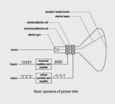
CRT (cathode ray tube) monitors. The intensity of the electron beam and the
brightness of the dot are determined by the voltage level of the external video
input signal, labeled mono in the following figure. The mono signal is an
analog signal whose voltage level is between 0 and 0.7 V.
A
vertical deflection coil and a horizontal deflection coil outside the tube
produce magnetic fields to control how the electron beam travels and to
determine where on the screen the electrons hit. The following figure shows the
CRT scanning pattern.
The
monitor’s internal oscillators and amplifiers generate sawtooth waveforms to
control the two deflection coils. For example, the electron beam moves from the
left edge to the right edge as the voltage applied to the horizontal deflection
coil gradually increases. After reaching the right edge, the beam returns
rapidly to the left edge (i.e., retraces) when the voltage changes to 0.
Video
controller
A
video controller generates the synchronization signals and outputs data
pixels serially. A simplified block
diagram of a VGA controller is shown in following figure. It contains a
synchronization circuit, labeled vga-sync,
and a pixel generation circuit.
The
vga-sync circuit generates timing and synchronization signals. The hsync and vsync signals are connected to
the VGA port to control the horizontal and vertical scans of the monitor. The two signals are decoded from the internal
counters, whose outputs are the pixel_x and pixel_y signals. The pixel_x and pixel_y signals indicate the
relative positions of the scans and essentially specify the location of the
current pixel. The vga_sync circuit also generates the video-on signal to
indicate whether to enable or disable the display.
VGA
Synchronization
The
video synchronization circuit generates the hsync signal, which specifies the
required time to traverse (scan) a row, and the vsync signal, which specifies
the required time to traverse (scan) the entire screen. This principle is based on a 640-by-480 VGA
screen with a 25-MHzpixel rate, which means that 25M pixels are processed in a
second. Note that this resolution is also known as the VGA mode. The screen of
a CRT monitor usually includes a small black border, as shown at the top of
following figure. The middle rectangle is the visible portion. Note that the
coordinate of the vertical axis increases downward. The coordinates of the
top-left and bottom-right comers are (0,0) and (639,479), respectively.
A
period of the hsync signal contains 800 pixels and can be divided into four
regions:


0 comments:
Post a Comment